ASCE 7 requires a defensible site class for every new structure in El Paso, and near the Franklin Mountains, the basin geometry changes fast. Seismic tomography—both refraction and reflection—gives us a continuous image of the subsurface, mapping the transition from loose basin fill to bedrock. We run these surveys across the Upper Valley, East El Paso, and out toward Horizon City, where the depth to the Rio Grande Rift basement can vary from 15 to over 200 feet in less than a quarter mile. The method measures P-wave and S-wave travel times, then inverts them into velocity layers. This directly feeds into Vs30 calculations and IBC site classification. It also flags buried faults, old alluvial channels, and zones of low-velocity fill that SPT borings alone can miss. Our field crews use 24- or 48-channel seismographs with vertical and horizontal geophones, depending on whether the target is simply rock depth or full shear-wave velocity profiling for liquefaction screening under liquefaction criteria.
A seismic velocity model turns scattered borehole data into a continuous cross-section, so you see what lies between the drill holes.
Methodology and scope
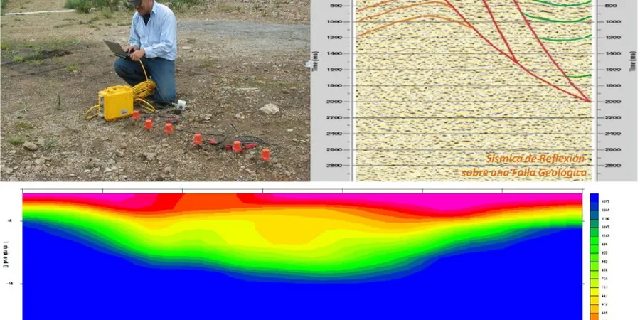
Local considerations
The El Paso metro area has recorded over 1,300 earthquakes since 2008, most of them small but a reminder the Rio Grande Rift is an active extensional basin. Site amplification here is strongly controlled by the thickness of unconsolidated fill over bedrock. Without a measured shear-wave velocity profile, the default IBC Site Class D assumption can penalize your design with spectral accelerations 30 to 60 percent higher than what the ground actually delivers. We have seen projects where a single seismic tomography line reclassified a site from D to C, saving thousands in structural steel. The other risk is missing a buried scarp or a sharp lateral velocity change that concentrates strain during shaking. A 2D tomography line across the building footprint catches that. For critical facilities in the Northeast and Lower Valley, we also recommend tying the velocity model to a seismic microzonation study to meet ASCE 7-22 Chapter 21 requirements.
Applicable standards
ASTM D5777-18, ASTM D7128-18, ASCE 7-22, IBC 2021
Associated technical services
P-Wave Refraction for Bedrock Depth
A 24-channel spread with a 230-ft cable, hammer or weight-drop source. We pick first arrivals, run a tomographic inversion, and deliver a velocity cross-section showing the top of competent rock. Ideal for shallow foundations and pipeline alignments in the foothills.
MASW + Refraction for Vs30 and Site Class
Combined active-source surface wave and refraction survey using 4.5 Hz geophones. We extract the fundamental-mode dispersion curve, invert for 1D shear-wave velocity, and compute Vs30 per NEHRP guidelines. Used for every IBC site classification in the basin.
Cross-Hole or Down-Hole Seismic Tomography
For deep foundations or critical infrastructure, we run down-hole surveys in a cased borehole with a shear-wave source at surface, or cross-hole between two cased holes. Provides a high-resolution velocity log for dynamic modulus and deformation analysis.
Typical parameters
Frequently asked questions
How much does a seismic refraction or tomography survey cost in El Paso?
Budget between US$2,480 and US$6,020 for a typical survey. A short P-wave refraction line with a single spread and hammer source runs at the lower end. Longer lines with roll-along, combined MASW for Vs30, or reflection processing push toward the upper end. Access constraints in the Franklin Mountain foothills or on TxDOT right-of-way can add mobilization costs. We provide a fixed-price proposal after reviewing the site footprint and target depth.
Can seismic tomography replace boreholes for site classification?
Not completely—the IBC still requires a boring for soil description and laboratory testing. What tomography does is fill the gaps between borings and provide a measured Vs30 rather than a correlation from SPT N-values. The combination of one or two borings plus a seismic line almost always yields a more defensible site class and can reduce the number of borings needed on a large site.
What depth of investigation can you reach in El Paso basin sediments?
With a standard 230-ft spread, refraction tomography reliably images to about 80–100 ft in the basin. For deeper targets—like mapping the Hueco Bolson fill to 300 ft or more—we use a roll-along spread with a heavier source or switch to reflection acquisition. The limestone bedrock along the mountain front usually generates a strong refraction at any depth we encounter in the metro area.